Teensy is a microcontroller development board used for building all sorts of awesome DIY electronic projects.
Over the last year I’ve been designing 2 new Teensy models using far more powerful microcontroller chips; a huge step up in capability from prior Teensy and other Arduino compatible boards. Now, hopefully with your backing, it’s time to move from development & prototype phase to the first production run of these new, much more powerful products.
The scope of this Kickstarter project involves completing a first production run and publishing good Arduino-compatible support software, with these 2 new Teensy boards as the physical rewards shipped to backers.
However, this new hardware is meant to be a stepping stone to open an ambitious new chapter of software design & platform enhancements. As I’ve done with Teensy for many years, I intend to develop increasingly powerful but easy-to-use software libraries and even improvements to the Arduino platform to enable everyone to more easily create awesome, incredible DIY projects.
A Brief History of Teensy
Teensy has always been about bringing more powerful microcontroller features to the DIY Electronics world, not just hardware, but advanced libraries that allow more powerful features to be used easily from Arduino.
Teensy 1.0 (late-2008) offered 12 Mbps native USB at a time when all Arduino compatible boards used slow serial. It was the first board Arduino compatible board to feature very fast USB communication.

Teensy 2.0 (2009) added support for USB Keyboard, Mouse & MIDI. At this time nearly all Arduino libraries were hard-coded for Diecimila/Duemilanove. In 2010-2011, I added thin abstraction layers to Servo, Firmata, OneWire, IrRemote & many more, as well as fixed many issues and optimized code, which later paved the way for compatibility for later Arduino products (Mega, Leonardo, etc). Starting from this early period, I contributed many optimizations & improvements back to Arduino, to benefit everyone, not just Teensy users.
Teensy became more widely used from 2011. So did the early addressable LED strips. Inspired by a conversation with Phil Burgess, I created code to stream USB packets to LEDs. This pushed Teensy 2.0 to its technical limits, but several people used it to build some awesome LED projects.

Teensy 3.0 (2012) was the first 32 bit Teensy, launched here on Kickstarter. While Maple deserves the credit for being the first 32 bit Arduino compatible board, Teensy 3.0 began a major effort to port every widely used Arduino library and begin developing new libraries to truly use the far more capable hardware.

By early 2013, much less expensive addressable LEDs appeared. Many people were interested in using them for video walls, inspired by those earlier projects. At first this seemed impossible due to their tight timing requirements. But using the flexible DMA controller and timers in Teensy 3.0, I created the OctoWS2811 LED library which has been used by many thousands of people to create truly outstanding large LED products.
Small color TFT screens also became inexpensive around this time. At 320×240 resolution, these update quite slowly using 8 bit microcontrollers. Running the same code on Teensy 3.0 results in a 3 to 4 times speedup. But by developing a special optimized library to take advantage of the more sophisticated hardware FIFO and control signal hardware, much better performance was achieved.
Teensy 3.1 & 3.2 (2014) Teensy was updated to a faster chip with 4 times larger RAM. The increased memory size opened up the possibility of very flexible audio. I spent nearly 2 years developing the Teensy Audio Library, which is actually a toolkit of dozens of audio processing components. To help people use it, I created this design tool, borrowing GUI code from the Node-Red project.

With some help from Alysia Dynamik, in late-2015 we created a workshop and tutorial demonstrating many of the audio library features. This video walkthough can give you a good idea of how I’ve tried to put this 32 bit hardware to use, crafting a library that not only makes audio processing possible, but easy to do from Arduino sketches.
Since this video was made, several more audio features have been added, including quad channel input & output and USB audio streaming, where Teensy appears to your PC as a USB sound card and audio data streams bidirectionally between your PC and the audio library.
Each new generation of more capable Teensy hardware has brought the opportunity to develop these advanced libraries. Now, hopefully with your backing, it’s time to again step up to more powerful hardware.
Technical Features & Specifications
Features specific to Teensy 3.6:
- 180 MHz ARM Cortex-M4 with Floating Point Unit
- 1M Flash, 256K RAM, 4K EEPROM
- Microcontroller Chip MK66FX1M0VMD18 (PDF link)
- USB High Speed (480 Mbit/sec) Port
- 2 CAN Bus Ports
- 32 General Purpose DMA Channels
- 11 Touch Sensing Inputs

Features specific to Teensy 3.5:
- 120 MHz ARM Cortex-M4 with Floating Point Unit
- 512K Flash, 192K RAM, 4K EEPROM
- Microcontroller Chip MK64FX512VMD12 (PDF link)
- 1 CAN Bus Port
- 16 General Purpose DMA Channels
- 5 Volt Tolerance On All Digital I/O Pins

Features common to both:
- 62 I/O Pins (42 breadboard friendly)
- 25 Analog Inputs to 2 ADCs with 13 bits resolution
- 2 Analog Outputs (DACs) with 12 bit resolution
- 20 PWM Outputs
- USB Full Speed (12 Mbit/sec) Port
- Ethernet mac, capable of full 100 Mbit/sec speed
- Native (4 bit SDIO) micro SD card port
- I2S Audio Port, 4 Channel Digital Audio Input & Output
- 14 Hardware Timers
- Cryptographic Acceleration Unit
- Random Number Generator
- CRC Computation Unit
- 6 Serial Ports (2 with FIFO & Fast Baud Rates)
- 3 SPI Ports (1 with FIFO)
- 4 I2C Ports
- Real Time Clock
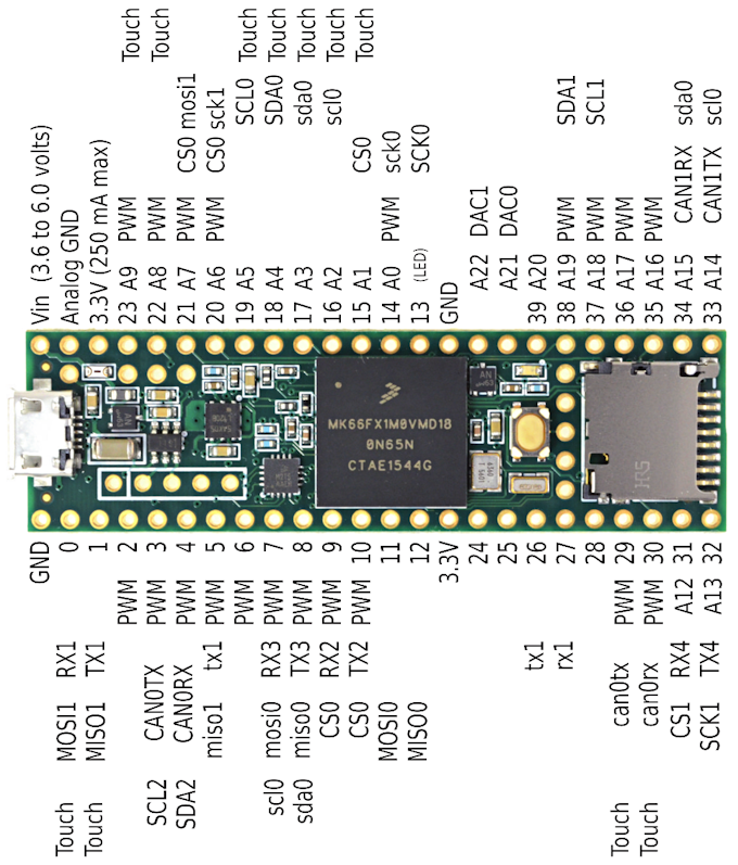
- The pin assignments have been designed to preserve compatibility with the 28 breadboard-friendly pins of prior Teensy 3.x models. All 28 of these pins support the same features as the older models.

More I/O pins are available at small surface mount pads on the back side. The 6th serial port, 4th I2C port and 3rd SPI port are on these pins. They’re not as easy to access as the main 42 through-hole pins on the outside edge, but for projects where you really need access to a huge number of I/O signals or those extra communication ports, these boards do give you a way to access them (but keep the board to a reasonably small “Teensy” size).

Teensy 3.6 has a second USB port which is capable of 480 Mbit/sec speed. It’s intended to used in USB host mode, so you can connect USB devices like a keyboard or memory stick. This USB port is accessed using 5 pins, which are compatible with the commonly available internal PC cables for USB.

The Arduino IDE is the primary method used to program Teensy. Like prior models, my goal for Teensy is the best possibility compatibility with all Arduino functions and widely used libraries.

Development Timeline
I started planning for a high-end Teensy about 3 years ago. This paper model was among the very first steps. This paper model was made before Teensy 3.2 existed (early 2014), when we were still using the Mini54 chip to implement the bootloader. It has sat on the corner of my desk all this time, as a reminder to make a more capable Teensy model.

As you can see, the concept of a 48 pin breadboard friendly form factor with the micro SD socket existed from the very early days. Originally 10 more through-hole pins were planned between the pushbutton and chip, with 8 of them providing the last Serial, I2C & SPI ports. You can see these 10 pins on all the later prototype boards, but they were ultimately changed to to bottom-side SMT pads to allow room for the USB host port.
This circuit board is the first prototype which actually worked, made in early 2015. A few others were made earlier but didn’t work and were never debugged. As you can see from the white wire, this version also had some mistakes.

NXP/Freescale published datasheets for the MK66 chip in mid-2015 and the chips became available in late-2015, long after this prototype was made with the earlier MK22 chip.
To say this early prototype “worked” may be a bit of an exaggeration. I had quite a bit of trouble with my code and the newer flash memory controller. NXP/Freescale calls this controller “FTFE”. The ones in other Teensy models are “FTFL” and “FTFA”. Their documentation looks very similar, but subtle differences set my efforts back by many months. FTFE only supports 64 bit word size. It also seems to have very strange undocumented behavior in some conditions, which aren’t treated as errors at all by the smaller FTFL & FTFA controllers.
Two more prototype boards (no photos) were made, based on the update from the MK22 chip to MK64 & MK66. The pin assignments changed somewhat, mostly to allow an Ethernet PHY shield to use the on-chip Ethernet peripheral. The extra power pins were brought near the center of the board, to see these connections short for a future Ethernet shield, which would require the RMII interface which clocks at 50 MHz.
In May 2016, the last prototype was adapted to make this beta test board. It has the final pinout with sockets added at the intended form-factor.

In June, we began a beta test period, first sending 10 of these boards to long-established community contributors in mid-June, and another 16 later in July. As you can read in that incredibly long forum thread, a pretty tremendous amount of beta testing has occurred over the last couple months!
Before finalizing the pinout, I wanted to be absolutely certain we could have a working Ethernet shield. The RMII signals seemed simple enough, but lingering questions remained about the RMII clock. So in July I designed this Ethernet shield using the LAN8720A chip.

I was able to write and confirm a simple ping sketch. Some of the beta testers, especially forum user Manitou, stepped up to do much more testing, including benchmarks that show the hardware really is capable of back-to-back packet processing at 100 Mbit/sec speed!
A pretty incredible amount of testing has been done over these last two months, including impressive benchmarks on the native SD port and some initial results with the 480 Mbit/sec USB port. Most of the Arduino libraries have been ported or updated.
In July I turned my attention to the PCB layout. The design uses 6 layers. Cramming all this into the Teensy form-factor, routing so many signals from the 144 ball BGA using “escape routing” mostly on just 2 sides without any other PCB area for signals to cross back to the other side of the PCB was quite a challenge. This was by far the most difficult PCB layout I’ve ever done. After a few solid weeks of work, it was finally all routed, even preserving 2 of the layers for only ground and power planes.
As you can guess by the purple color of my prototypes, I love OSH Park, and I tend to make many iterations as I work on a project. But they don’t offer a 6 layer service, nor small slots which I wanted to use for a strong USB connector. It seems nearly all 6 layer prototype services are quite expensive. We ended up having our normal PCB vendor make the 6 layer prototype in the form of the actual panels we’ll use for production.

All Teensy 3.x boards are assembled in the USA, at a local contract manufacturer that’s only a 15 minute drive away. Robin and I met with them, and they were eager to do a test run, especially since this our first PCB with this BGA chip and the USB connector using slots.
The boards from this pre-production run work great, I was quite relieved to learn after making this small run of boards using a brand new PCB layout (have I mentioned how much I wish for OSH Park’s awesome service for 6-layer boards). The final production boards will be identical, with the minor exception of those extra holes in the panel frame were relocated, to better fit special fixture equipment they use with applying the solder paste.
Even though most of the technical work to design this board is completed, much work remains to be done for a final release. How we will test these is the next major task as we fully test every board before shipping them out. Much work also remains on documentation everyone needed for a properly supported development board. I’ll be writing updates. These high-end components and 6 layer boards also involve quite a financial investment (PJRC is a tiny company, just a few people) which is where the magic of Kickstarter comes in. We’ll gauge the size of this first production run of boards based on the response here, so I hope you’ll consider backing this project to help us complete the last step of a full production release.
Future Software Development Goals
Teensy has always been about so much more than just its hardware, about bringing more advanced but easy-to-use software libraries to the Maker & DIY hardware communities. In this last section, I’d like to share some of my ambitions for where this far more powerful hardware can take us.
Kickstarter requires all projects to have clear goals, to be able to define a point where the creator can say “it’s finished”. For Teensy 3.5 & 3.6, that goal is shipping all the rewards, and a non-beta software release that provides compatibility with all the standard Arduino functions, libraries that come built-in to Arduino, and the 76 of the 77 other commonly used Arduino libraries that ship with Teensyduino 1.29 (one is specific to only 8 bit AVR). These should not be considered part of completing this project.
- USB Types for MTP Disk, USB ethernet
- Audio library, many ambitious ideas: network in/out streaming, real-time pitch shifting (phase vocoder), tempo/beat analysis, granular synthesis & effects, etc
- LED music visualization (prime use of the floating point unit)
- SD library to use DMA and pre-fetching, thread/interrupt safe caching
- Ethernet library, drop-in replacement for Arduino’s Ethernet lib
- Arduino Event Processing API
- USB Host Library Exansion & optimization
- Debug features integrated into the Arduino IDE
While some work has been started on a few of these, most of these are “wish list” ideas. Much of the best work I’ve done for Teensy over the years, such as the OctoWS2811 library for video-speed control of large LED projects as been inspired by comments. So please do comment. It really can lead to great things!
Risks and challenges
Manufacturing of any hardware can involve risk of delays. Vendors may deliver materials late, assembly issues can lead to setbacks, and issues with testing, package and shipping can come up.
PJRC (my small company) has 16 years of experience manufacturing and selling microcontroller development boards, and I personally have 24 years of professional electrical engineering experience. Many people who backed the Teensy 3.0 Kickstarter in 2012 have commented it was one of the few campaigns they’ve ever seen ship on time. We recently completed a tiny preproduction run of beta test boards, which builds a high degree of confidence we will be able to manufacture these boards without significant delays.
I am confident we’ll avoid such issues, based on how well the pre-production run went. It’s a major personal goal of mine to see every single reward shipped on time! But unforeseen issues can always come up. If they do, we certainly do have the resources and experience to quickly deal with setbacks.
The short-term software goals, excellent compatibility with Arduino and widely used Arduino libraries are looking very promising. Beta testing over the last 2 months has already resolved many issues, with nearly all libraries confirmed working. Of course, software is notoriously difficult to ever become absolutely bug free.
Long-term future software development goals, while not technically within the scope of this project’s rewards, are of course important. They’re also very ambitious ideas which may take a very long time, or may change in scope, or may not come to fruition. I do have a good history of developing these sorts of software projects, but no particular grand software idea is ever 100% certain until it’s actually implemented.
